
Almost every single racing vehicle have Power Distribution Module. From a Simple Fusebox until advance Power Distribution Controller. PDM is quitely as important as ECU for vehicle. I am interested to review and compare it. Just review it based on their specification.
Before review PDM from variety Manufacturer, we should know some basic of Power Ditribution Modules Design.
Basic Design of Power Distribution Module
Basic design of Power Distribution is simple. It should have switch, Fuse, Load. And There’re some sequence of circuit above. This showed Below


As showed above, the difference is only position of switch. Based on My experience, HIGH SIDE sequence is common used.
The other components beside fuse, switch, load are may feature of PDM, and it will create unique signature from many manufacturers. And we will showed some that variety. I divide it to Classic Fuse Box, Fuse box with relay, FET PDM, Adjustable Fuse PDM, and Complex Advance PDM.
Classic Fuse Box
This type is pretty simple, just like basic of PDM. still exist in marketplace. And ez to use. This circuit are showed below

it looks simple, but cant applied to high power/High Current load. Because it directly flow current to switch that contacted by Human and it is danger. And to prevent it, we continue to Fuse box with Relay
Fuse box with Relay
said before, this type is safer than classic fusebox. this circuit is showed below

This circuit more friendly, because switch only pass low current. Smaller than current that direct flow to LOAD. the low current depends on Relay coil’s impedance.
With scheme above, User can use variety switch and more dynamic scenario. From Mechanical switch, or maybe Sensor Switch. it depends on user’s needs.
Fusebox with relay offers ez and safer option for Power Distribution Module. This type are commonly used by many Vehicle Manufacturer, maybe we can see in our own car/motorsycle. Because it is cheap technology, and solve some problems.
But we know, Relay are electromechanical component. There’s an Mechanical process. for some case, it doesnt handle mechanical noise like vibration, or maybe collision. My friend cant sleep over night to troubleshoot his motorcycle’s problems. His Motorcycle’s relay switched when faced street potholes hahaha.
For issue above, it solved by FET PDM.
FET PDM
The scheme is same like Fusebox with relay. but it replace relay with Semiconductor Component, like BJT, but commonly MOSFET.
Unlike before, This type is full controlled by electronics. Maybe only switch that controlled by mechanic process.But overall it minimize mechanical noise, but maybe replace by electrical noise. But it’s okay, more ez to control
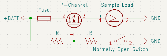
Unlikely relay based switch, different sequence type(High side/Low Side) is using different type of MOSFET. High Side switching using P-Channel MOSFET, Low side switching using N-Channel MOSFET. Maybe because of Vgs trigger that controller MOSFET. As mentioned, High side type is common used, and P-Channel MOSFET is more expensive than N-Channel.
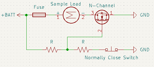
This type is common used by modified car as upgrade. And this type is more expensive than fusebox with relay. And this type can upgrading to “Adjustable Fuse” Power Distribution Module, that describe below.
Adjustable Fuse PDM.
Adjustable Fuse doesn’t mean it has fuse that can change its current limit. Additional current sensor and microcontroller, make it happen. Microcontroller reads current, and when it’s over than user’s limit, it will cut off switches directly. PDM with current sensor and microcontroller makes pretty good feature.
This feature allow user can “adjust” fuse limit without changing fuse hardware. We can change current limit by software. And this benefit enable us to change current limit with wide range current value. We can limit at 15.1 A, or 12.9 A, or 18.7A, or whatever fucking current limit value, dude. it’s awesome.
It still has Hardware fuse. But using highest current limit in single channel. Like the idea of fuse, protect short circuit on Load, and also MOSFET, and also the current sensor. The circuit is showed below.
+Vbat — FUSE — Current Sensor — MOSFET — Load — GND

Features above is overkill for PDM. and mentioned above, additional current sensor means additional cost. Of course it will be more expensive. But I am going to describe boss of expensive PDM feature.
Complex Advance PDM
There is it, Boss of PDM. It just add Communication between electronics module. Most common is applying CANBUS communication. It only need 4 cable, or even 2 Cable. There are connecting CAN H, CAN L, Power(Optional), ground (optional). Even there’re are dozens input for switching, it need 4 cable for CAN bus to connect between input module and PDM.
besides CAN bus, Manufacturer add logical function for switching load. It’s allowing us to create complex scenario like starting engine maybe. Or an cool scenario for open vehicle’s car. Or maybe for controlling Hydraulic suspension valve to make car dancing like a GTA San Andreas’s mission.
The design of this type is showed below.
[Diagram Block of design]

This type are Former type PDM by Power Distribution Module than 2 types before. Because Microcontroller/Processor has bundled feature like ADC, I/O, and CAN Bus, so Manufacturers maximize this feature to develop advance complex PDM. But I don’t know exactly, I never have PDM, just curious about it.
Next time, i will write comparison about real PDM. and also guess what inside it.
